
I decided to build an electric guitar. The reasons no longer matter and in fact this guitar didn’t even turn out that well. I made many, many mistakes but I finished it and in so doing, learned enough to build the next one even better. And so on, and so on, and so on.
I’d always wanted a Telecaster Deluxe with two humbuckers and so that is what I decided to build. Now about those humbuckers…
A “pickup” is the name for the device on an electric guitar which picks up the vibrations of a moving guitar string and creates a electrical signal which can then routed to an amplifier. The easiest way to understand a pickup is to think about the electromagnet you might have made as a kid. Or, like me, maybe the electromagnet you made for your kid. Remember? The big nail wrapped in wire and then connected to a giant battery? When the circuit was completed, the nail became a strong magnet and it could pick up steel things, like paper clips, smaller nails, etc.
Well a guitar pickup is similar to that but in reverse. In this case, instead of running electricity through the wire wrapped nail, you move a piece of steel (the guitar string) near a wire wrapped magnet and this produces a very faint and very weak electric signal in the wire coils surrounding the magnet. So instead of producing a magnetic field via electricity, when the steel strings move near the wire wrapped magnet, they produce an electric current. So electric pickups don’t “hear” a physical sound. They “hear” electromagnetic waves and turn that into electricity. You could say they hear radio waves. The sound produced by the strings and the wooden body and neck is incidental.
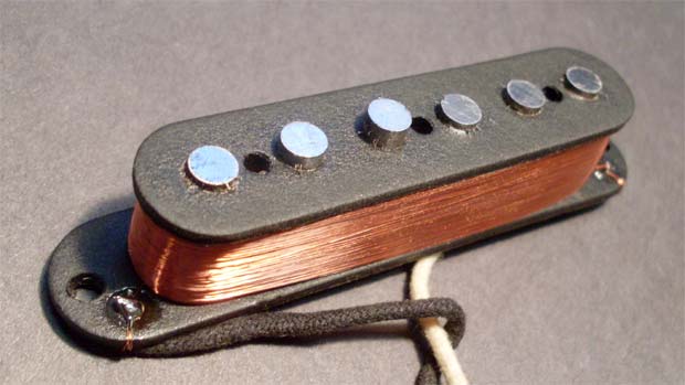
The problem with this simple design for a guitar pickup is that coils of wire also make an excellent antenna and so they pick up lots more than just the moving guitar strings. They pick up neon sign hum, AC power hum from your home, florescent lights, the motor in your fridge, etc. You hear this as a background hum in your amp and it can be pretty annoying, especially if it is loud. There are a few ways to deal with this and I’ll discuss another way in a future post but for now, I want to mention the mighty humbucker. The humbucker was invented in 1934 for use in PA systems and later in amplified pianos. In 1955, Gibson patented the humbucking pickup for guitars and of course the Gibson Les Paul was the first guitar to use humbuckers in mass production.
How do they work? On a single pickup, the polarity of a voltage induced in the pickup by the moving guitar string depends on the direction of the coils around the magnet and the direction of the magnet. A humbucker typically consists of two pickups, with the magnets in opposite directions and the wiring reversed. As a result of these two negative changes, the moving guitar strings generate the same signal in both pickups. Combining them results in a powerful signal. But the electromagnetic interference, from the neon signs and motors and stuff generate their own signals but only correlated to the direction of the wire winding, and not to the magnet direction. As a result, each pickup generates an interference voltage which is completely out of phase with the other. When these voltages are summed, by combining the pickups, the result is that the interference signals cancel out, leaving only signal – no hum. Hence the term humbucker.
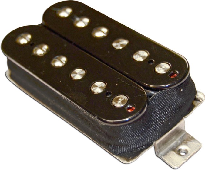
One thing Jimmy Page and others soon realized was that this boosted signal, coming from having two single coil pickups wired in series also produced a much louder signal. A high-output pickup sends a stronger signal to the amp, which means the amp distorts more readily. So humbuckers also ended up being the pickup early guitarists used when looking for better and more extreme distortion sounds.
For the Frankencaster, I chose two Seymour Duncan pickups, a model 59 for the neck and a JB for the bridge. My hope is that the JB is much “hotter” than the 59 and that I am going to see some serious crunch when playing on the bridge pickup.
The next trick is to figure out how to wire this guitar.
I was trying to think about how to discuss the guitar wiring. I know wiring diagrams and electronic components can be rather opaque to many people but they really aren’t that hard. I decided not to go into any kind of theory but just to look at my wiring diagram/proposal to see how things will work. Remember, electric guitars are, well, full of electricity. And electricity likes to flow. In many respects electrons flowing in a wire are just like water flowing in a pipe and in fact that’s how I’ll analyze my Frankencaster wiring diagram below.
When I realized I would need to connect all these components, I looked at various wiring diagrams on the web thinking I could just quickly borrow one. What I found was that they were all different and so I quickly realized I would need to do my own. I think I understand how to wire a guitar so I drew up the following schematic which I plan to use to wire the Frankencaster. I drew this diagram on a plane flight to Seattle and let me tell you I drew a lot of glances from the guy sitting beside me. I think he thought I was working on a bomb diagram. I was very tempted to start running my finger down a specific wire and then softly whisper “BOOM”.
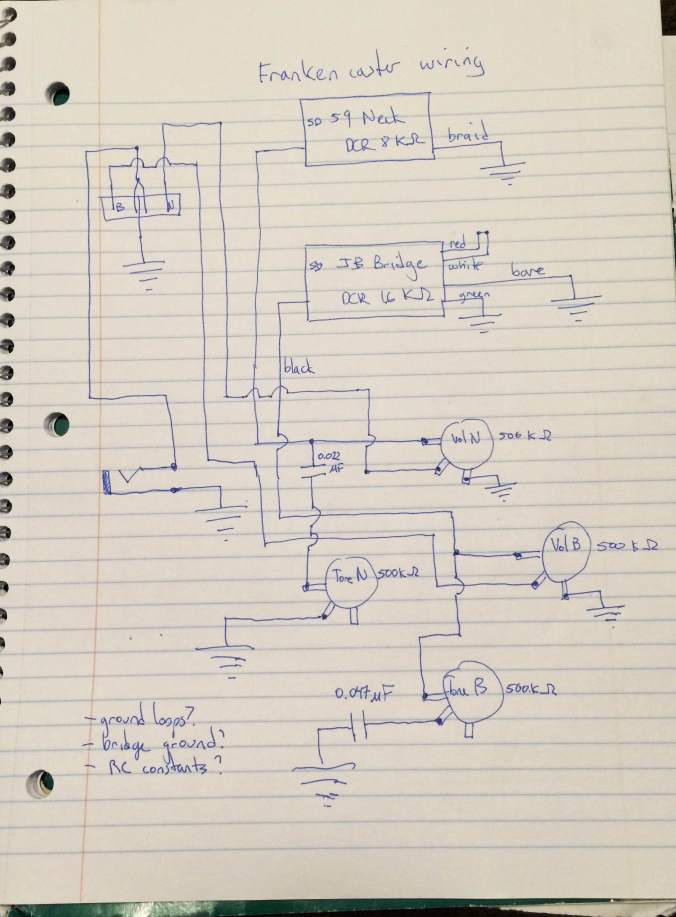
The way to understand this schematic is to remember that electric signals want to flow from source (pickup) to ground, completing a loop, or circuit. The symbol for ground in the schematic looks like an upside down Christmas tree or pyramid and you read this symbol as saying all the grounded things share a common connection, which joins them electrically. You can imagine them all connected together by a big loop of wire though in practice that won’t be how I ground the components (see below).
In this wiring diagram, there are 10 basic components. There are two pickups (neck and bridge), each with its own volume control and its own tone control. These volume and tone controls are made from potentiometers, or variable resistors. A variable resistor, say 500 K ohms, is exactly what it sounds like – you turn the knob and this varies the resistance between the middle post and an outer post from 0 ohms (conductor) to 500,000 ohms. So that’s six components.
Each tone control also uses a capacitor (which adds two more components). Capacitors, in this context, can be thought of as components which, when combined with resistors, allow a direct connection to ground for certain frequencies. In other words, capacitors in series with resistors can subtract certain frequencies from the main signal, shorting them to ground before they get to the output jack. These circuits are called “filters”. By changing the resistance, one can change the frequencies which are subtracted. This is how a basic tone control works. Turning the tone knob alters the resistance and changes the frequencies removed from the signal from none to some. What you actually hear is treble being added or lost. In fact no treble is added, it is only removed.
Then there is a switch to switch between the two pickups, and finally there is an output jack, where the signal goes out to the amp and later returns to the guitar and to ground. Each of the pickup circuits is independent of the other so while they make the diagram look more complicated, it is really just two circuits on the same page, sharing a switch.
For the volume controls, the voltage from the humbucking pickup enters the variable resistor and leaves through the wiper (middle lead) of the variable resistor. If you turn the pot all the way in one direction, and the voltage may be zero; turned to the other side the output voltage approaches the input voltage. This is how the volume control changes the volume, by reducing the output voltage to near zero.
There are three questions at the bottom of the page and I’ll briefly mention them as they were items I wanted to research further. First, I want to make sure the end result had few to no ground wire loops. For example, both volume controls have one lead connected to ground. By connecting a wire between then and then running the wire to another place to ground the components, potential ground loops are created. Ground loops are potentially bad because, since they are wires, it is possible to induce currents in them inadvertently (the same ways we induced currents in the pickups). The result can be a significant source of noise or hum. What I have decided to do is to wrap the body cavity and the entire underside of the pickguard with copper tape, thus at once grounding the various bits as well as providing a shielding cage around all the electronics. I’ll post pics when I get that done.
I will use the same solution for the bridge ground – tape overlapping the bridge to ground the bridge.
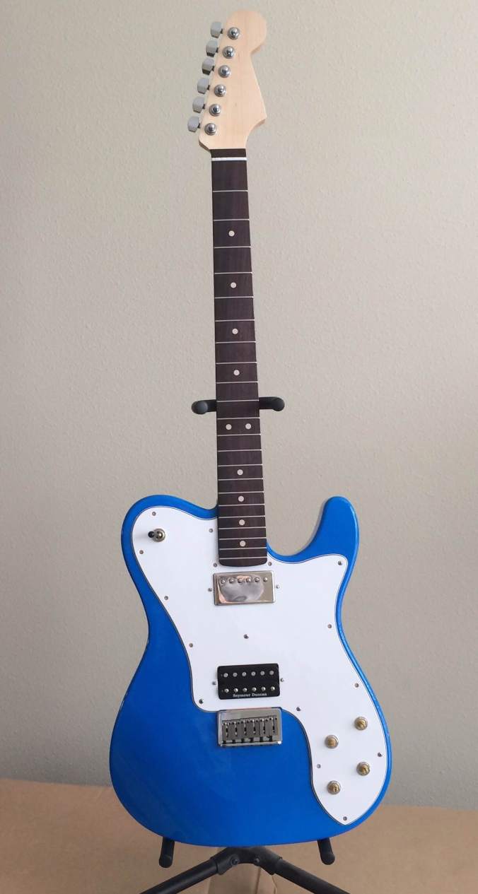
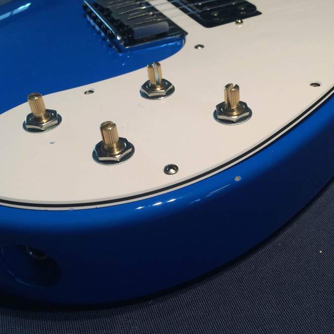
Let’s see where we are. Stuff is mostly bolted together but not yet working.
Next thing is to string to pitch and then do a basic setup. But first I want to show you one of my many mistakes. I chipped the damn finish! See below.
Now the guitar is intonated, it holds a tune, and it plays. But so far it’s only acoustic! Can it be electric?
Well, I plugged it into an amp. And guess what? Nothing. Literally nothing. No sound, no hum, no nothing. It is quiet beyond my wildest dreams. Except that I wanted to hear something. So, now it is debug time. Since I designed the wiring myself, I need to make sure I have wired the parts according to the wiring diagram, and then I need to make sure the wiring diagram is correct. To do all this, I’ll need to take the pickguard completely off which also means taking off the neck. So here we go.
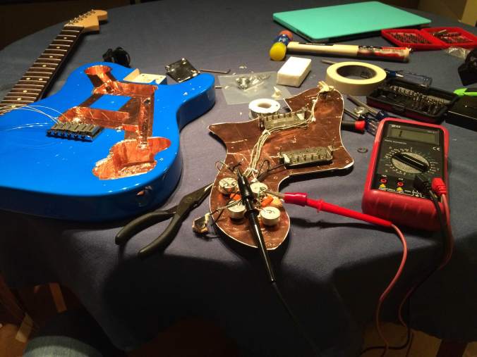
In case you are wondering, the colorful hammer you see is in case I lose my temper and need to bash the shit out of the pickguard.
Anyway, I started out debugging by making sure that things I thought were connected were connected and that things which shouldn’t be, aren’t. And what I found is that I have at least two shorts. A short circuit, or “short” for short, is when you have a zero resistance conductive path between two points which themselves should not be connected. Electricity always takes the path of least resistance and so no currents flow where they should flow, instead they flow through the short circuit. This basically renders any electrical circuit inoperable and sometimes dangerous.
The shorts in my case appear to be due to the stupid shielded cable I used. I used shielded cable, which is a cable with a conductor inside an insulator, like normal wire, but then with a third layer consisting of a conductive shell around the insulator. I used this cabling because I wanted to build a zero hum guitar and shielding the wires is the best way to make sure induced currents are not a noise problem. And also because it came in the kit and what else would I do with it? But as I mentioned previously, shielded cable is a total pain to work with. My shorts occurred because when I stripped off the insulation and the shielding, I believe I have accidentally exposed the conductor to the shielding, which instantly grounds the conductor, producing a short circuit.
I am afraid there is no quick fix. I am going to need to rewire the stupid pickguard using brand new wire which is not shielded. Maybe there is a way to effectively work with this stupid cable but if so, I don’t know what that is. So I am going back to standard wire, which I understand.
OK, Today I rewired the pickguard underbelly, or at least I replaced all the wires which were previously wired using the shielded cable. I went to my local hardware store at lunchtime and bought a role of 16 gauge stranded and insulated copper wire and replaced all the shielded cable. Taking the pickguard off means taking off the neck and the strings etc so this is not a tiny job but I did it. Unfortunately I didn’t take photos of this because I am starting to get very irritated at removing and replacing the pickguard several times a day.
Then as I put the guitar back together, I wondered how I might test the system without needing to re-assemble everything. It’s a bit of a quandary. I need something ferromagnetic which vibrates hundreds of times per second that I can use to generate a signal on the pickups. Hmm. Maybe a tuning fork would work? Sadly I don’t own a tuning fork. Later in my guitar building career I would realize you only need to bang something metal on the pickups to test them but at this time, I was still a purist 🙂
Anyway, I put the guitar back together but tested the new wiring as early as possible, which meant just after I had the neck back on and one string installed. If anything is still wrong, I need to minimize the time to getting back inside the guitar cavity.
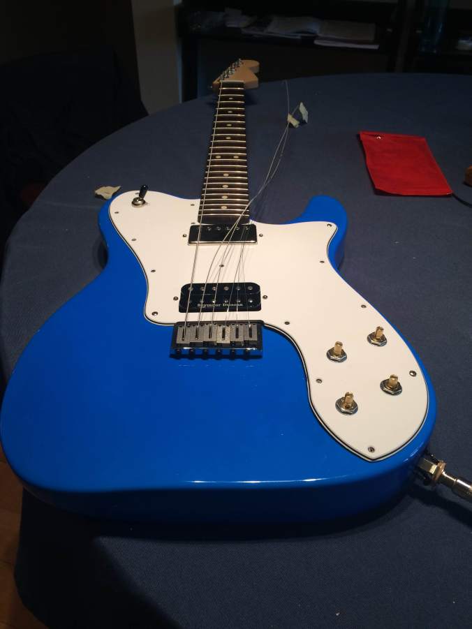
You’ll see the jack is not installed yet either – it is sticking out of the guitar. Two great bits of news. First, there is sound! And second, it’s the right sound!
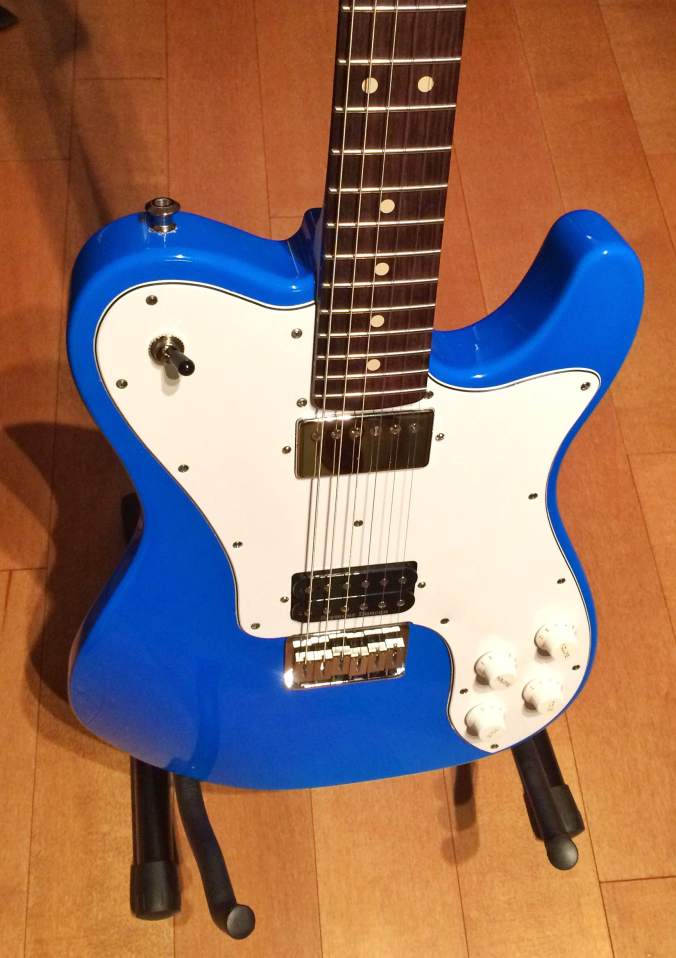
Success!
I quickly threw on the strings, tuned it, and tried to see how these mighty humbuckers sounded and they sound great: deep, resonant, mournful.
The other thing I elected not to write about were my screw misadventures. I broke several screws off in the body, including the screw to attach the strap mount and fixing those problems was quite challenging. I struggled for a long time to fix this problem, frequently making things worse in my endeavors. I’ll leave out the gory details.
A brief diversion: A sonnet is a 14 line poem written in iambic pentameter. Typically, in an Italian sonnet, the first octave (8 lines) has one rhyme scheme (a b b a a b b a) and the final sextet has a different rhyme scheme (c d c d c d) . I know this because I have written Italian sonnets for my job. But why am I telling you this? Wait and see.
Anyway, I am done with my stupid screw adventure. It doesn’t look great but it works. Just don’t look too closely.
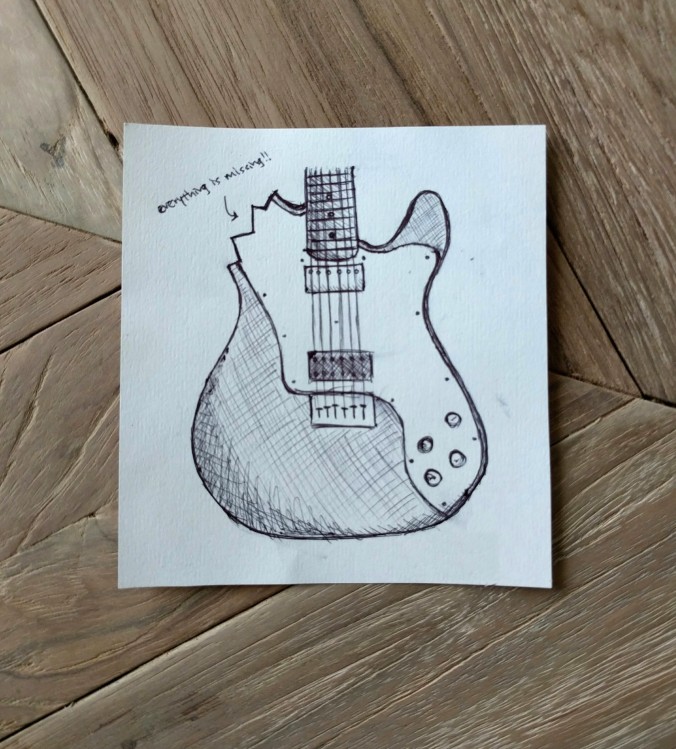
And as if that weren’t enough, I received this email from a friend:
“I took the liberty of drawing what I think your guitar will look like when you’re done “fixing” it.
To get closure on this abject misfire of a project end, I thought I would wrap up this tale by writing a sonnet to describe my adventure. I’ll apologize right now to Elizabeth Browning. Here goes:
How shall I extract thee? Let me count the ways.
I drilled thee to the depth and breadth and height
My drill can reach, when feeling sorry for my plight
For the chips of finish and too large holes.
I extract thee to the level of StewMac’s
Most useless tool, broken, in candle-light.
I extract thee freely, with tools born of OSH and night.
I extract thee purely, though I suffer great malaise.
I extract thee with the passion put to use
From my almost Telecaster, and with my chipped neon blue faith.
I extract thee with a love I seemed to lose
With mounting frustration. I extract thee with the breath, Smiles, tears, of all my life; and if God choose,
I shall never ever use a solid maple body because death.
Categories: guitar #1
Tags: Elizabeth Browning, italian sonnet, OSH, screw extraction, stewmac, telecaster

That’s a very funny post. Nice work!
LikeLike
No you just need to put that sonnet to music and include the recording on your newly built guitar!
LikeLike